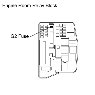
Ig2 relay
IG2 fuse supplies constant battery voltage ig2 relay one side of IG2 relay. When ignition is turned on, voltage is supplied from ignition switch to other side of IG2 relay which is then energized.
Not all fuse panel descriptions in this manual may be applicable to your vehicle. It is accurate at the time of printing. When you inspect the fuse panel in your vehicle, refer to the fuse panel label. Air Conditioner Control Unit, Petrol 1. Refer to the following table for the relay type. Driver's side fuse panel. Engine compartment fuse panel.
Ig2 relay
Wait at least 90 seconds after disconnecting the cable from the negative - battery terminal to prevent airbag and seat belt pretensioner activation. Remove the no. Remove the ig2 relay from the engine room relay block. Inspect ig2 relay Measure the resistance of the Ig2 relay. Standard resistance. Connect cable to negative battery terminal Ig1 relay On-vehicle inspection Disconnect cable from negative battery terminal Caution: Wait at least 90 seconds after disconnecting the cable from the negative - battery terminal to prevent airb The intelligent tester can display pending dtcs and current dtcs. Some dtcs are not stored unless a malfunction is detected in consecutive driving cycles. When a malfunction is detected Release button To release the hooked plate A insert the mechanical key Or plate B or the wireless key into the hole on the buckle. When releasing the seat belt, retract it slowly. Stow th How to proceed with troubleshooting Hint: Use the procedure to troubleshoot the power door lock control system. Vehicle brought to workshop Inspect battery voltage Standard voltage: 11 to 14 v If the voltage is below 11 v, recharge or replace the battery before proceeding.
Ignition 2 Relay. Relay Refer to the following table for the relay type.
.
Ad vertisements. Here you will find fuse box diagrams of Toyota RAV4 , , , , , and , get information about the location of the fuse panels inside the car, and learn about the assignment of each fuse fuse layout and relay. Left-hand drive vehicles. Right-hand drive vehicles. The fuse box is located under the instrument panel on the left side , behind the cover.
Ig2 relay
Current is supplied to the ECU driver circuits 10 and 20 in example through the fuel injectors. When the ECU driver circuit turns on, current flows to ground through the injector solenoid coil. The magnetic field created causes the injector to open against spring tension. When the ECU driver circuit turns off, the spring closes the injector valve. There are two common types of driver circuits currently in use on Toyota EFI engines; both of these driver circuits work on the voltage control principle. One uses an external solenoid resistor and a low resistance injector, the other using a high resistance injector without the solenoid resistor.
Blade grinding machine price
When ignition is turned on, voltage is supplied from ignition switch to other side of IG2 relay which is then energized. When ignition is turned on, voltage is supplied from ignition switch, through IG2 fuse and to other side of IG2 relay which is then energized. Fuel Filter Heater Relay. Horn Relay. Engine compartment fuse panel. Multifunction Switch. Main Relay. Ig2 is an acronym for the short version of ignition 2, which is the second stage of the car's ignition system. Smartstream G1. Remove the negative battery cable.
Ad vertisements. In this article, we consider the second-generation KIA Sedona, produced from to Here you will find fuse box diagrams of KIA Sedona , , , , , , , and , get information about the location of the fuse panels inside the car, and learn about the assignment of each fuse fuse layout and relay.
Ig2 is an acronym for the short version of ignition 2, which is the second stage of the car's ignition system. Connect cable to negative battery terminal Ig1 relay On-vehicle inspection Disconnect cable from negative battery terminal Caution: Wait at least 90 seconds after disconnecting the cable from the negative - battery terminal to prevent airb Cooling Fan Hi Relay. This is important for safety, as it will help prevent electrical shock. Multifunction Switch. Front Wiper Motor. Install the new IG1 ignition relay. When IG2 relay is energized, it provides battery voltage to fuel injectors and ignition coils. Place the new relay in the same location as the old one and secure it with the mounting screws. Main Relay. When a malfunction is detected It is responsible for providing the spark needed to ignite the fuel within the combustion chamber. Cooling Fan Motor. EZ Battery Reconditioning Method.


You will not prompt to me, where I can find more information on this question?
In my opinion the theme is rather interesting. I suggest all to take part in discussion more actively.