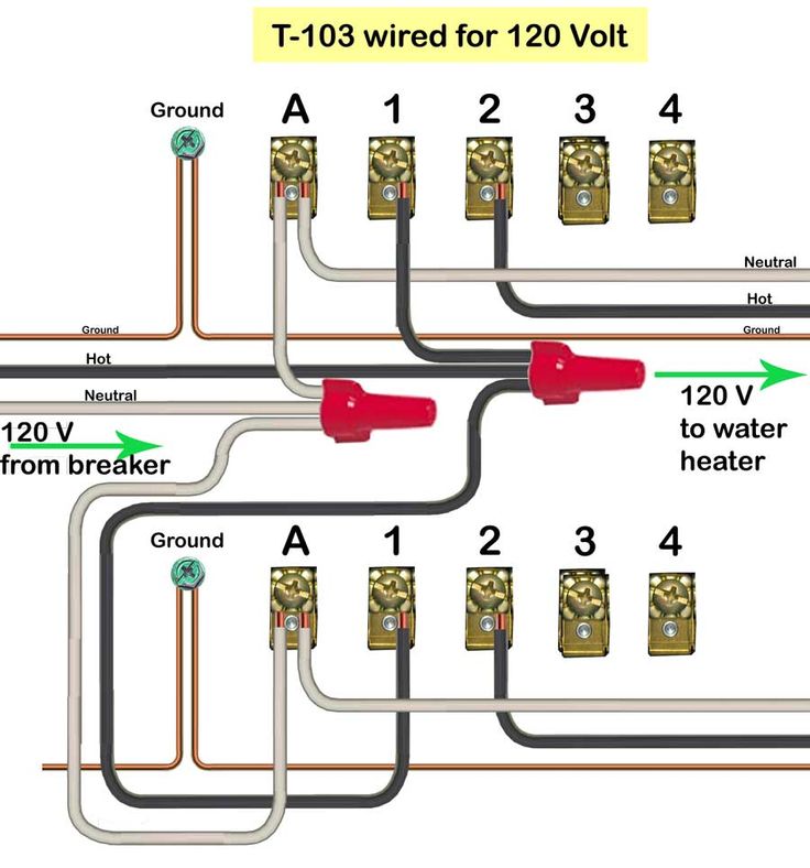
Intermatic timer wiring diagram
Forgot your Password?
Log in. Sign up. Jump to Latest Follow. JavaScript is disabled. For a better experience, please enable JavaScript in your browser before proceeding.
Intermatic timer wiring diagram
Running pool equipment 24 hours is usually unnecessary and expensive. Installing an Intermatic T timer is a great way to dramatically reduce run time and energy costs. The following steps will provide a guide on how to install the T timer. Note, timers vary with supply voltage. A T timer is used for V supply voltage. If you are using V supply voltage, you will need a T timer. The installation steps are the same for either. Toggle navigation Menu Cart My Account. Expert Advice: Chat Now or Call Hassle-Free Returns. Here are the instructions for how to enable JavaScript in your web browser. Once you've enabled Javascript, please refresh this page. Or give us a call at , and we would be happy to take your order by phone.
Yet you ignore it. Recommended Communities. Tighten screws very tight against copper wire.
Follow along with the video below to see how to install our site as a web app on your home screen. Note: This feature currently requires accessing the site using the built-in Safari browser. Search Everywhere Threads This forum This thread. Search titles only. Search Advanced search…. Everywhere Threads This forum This thread.
Running pool equipment 24 hours is usually unnecessary and expensive. Installing an Intermatic T timer is a great way to dramatically reduce run time and energy costs. The following steps will provide a guide on how to install the T timer. Note, timers vary with supply voltage. A T timer is used for V supply voltage.
Intermatic timer wiring diagram
Hide thumbs. Quick Links. Enlarged version. Troubleshooting Guide Observed Problem. The time of day or timer settings have not. Switch timer is in RANDom mode, which var-. The Astronomic and Specific switching times. For example, you've set ON to. Switch timer switches at incorrect times.
Maya colemann
It's amazing how what sometimes seems to be a 10 minute job can develop into a real head-scratcher. Intermatic timer Tp. It sure would have been nice if they would have labeled those two supply wires. Relays and Timers By Charles Ouellet. Multiple GFCI will cause tripping. AVS Forum. Terminals 1 and 3 are called the "Lines". The pool guy was not aware of the bypass switch and left it unconnected. The instructions give a typical two 3 way setup but yours may differ as to where power comes into the switching circuit. Thanks Reply. Replies 3 Views
.
Log in. This is the box with the red wire that had come loose marked S1 attached to where I think it belongs. I have been running all at V,.. Question Title:. I then need to identify the 3-way switch that has the power coming into it and put the timer into this location as the timer always needs power. Yet you ignore it. Then the V pool pump failed due to a scorpion intent on martyrdom that blue out the capacitors. T timer controls 3-phase Volt Volt timer Control V 3-phase using T timer Change V WG clock motor to WG clock motor Fused safety switch or disconnect required Timer turns on and completes circuit to contactor. Enjoying this content? The diagram shows that the COM is the connection that is switched. Also, check that the two supply wires from the breaker box are attached to terminals 1 and 3 and that the grounding wire from the box is attached to the grounding lug on the timer. Maximum 2 wires under same screw plate.


Rather excellent idea
I think, that you are not right. I suggest it to discuss. Write to me in PM, we will communicate.