P&id symbole
EdrawMax specializes in diagramming p&id symbole visualizing. Just try it free now! A piping and instrumentation diagram is more complicated than a process flow diagram.
A flow diagram is a simple illustration that uses process symbols to describe the primary flow path through the production equipment. It provides a quick snapshot of the operating unit and includes all primary equipment and piping symbols that can be used to trace the flow of the well stream through the equipment. Secondary flows, complex control loops and instrumentation are not included. These PFDs are more helpful for visitor information and new employee training. However, there are many other abbreviations that you will see such as this more comprehensive industry list. The number below these letters is the numerator to help identify a specific component on a project within the control loop. When there are multiples of the same device used in a diagram, this number helps viewers to reference that specific instrument.
P&id symbole
Piping and Instrumentation Diagrams are graphical representations of a process system. These are fundamental to every standardized engineering project. Piping and Instrumentation Diagrams detail the specific processes within a plant or industrial facility, including symbols that represent actuators, equipment, flow elements, instrumentation, piping fittings, valves. We recommend using the table of contents to navigate this comprehensive directory of common Piping and Instrumentation Diagram symbols. The symbols are organized in sections including equipment, fire and safety, flow elements, instrumentation, piping, valves, and more. Atmospheric tanks are containers for holding a variety of liquids at atmospheric pressure. There are various types as follows:. Compressors typically operate at a high pressure-to-volume ratio, while blowers operate at a low-pressure ratio. The most common driver used is the electric motor. Filters eliminate impurities from the passing fluid using physical, chemical, or biological processes to remove the contaminants. Heat exchangers are pieces of equipment used to transfer heat between fluids and can be used in both cooling and heating processes.
Check p&id symbolealso known as a one-way valve, is to prevent the line of medium back. As this diagram covers many types of diagrams as the variety in industries is vast, many symbols are required. Weight Operated Dump Valves.
Create powerful visuals to improve your ideas, projects, and processes. Work smarter to save time and solve problems. Helpful insights to get the most out of Lucidchart. Try Lucidchart. It's quick, easy, and completely free. The shapes in this legend are representative of the functional relationship between piping, instrumentation, and system equipment units.
Create powerful visuals to improve your ideas, projects, and processes. Work smarter to save time and solve problems. Helpful insights to get the most out of Lucidchart. Try Lucidchart. It's quick, easy, and completely free.
P&id symbole
These symbols can represent actuators, sensors, and controllers and may be apparent in most, if not all, system diagrams. The standard notation, varying from letters to figures, is important for engineers to understand because it a common language used for discussing plants in the industrial world. This section covers four main types of nomenclature. The first section describes the use of lines to describe process connectivity.
Aunt cassy r34
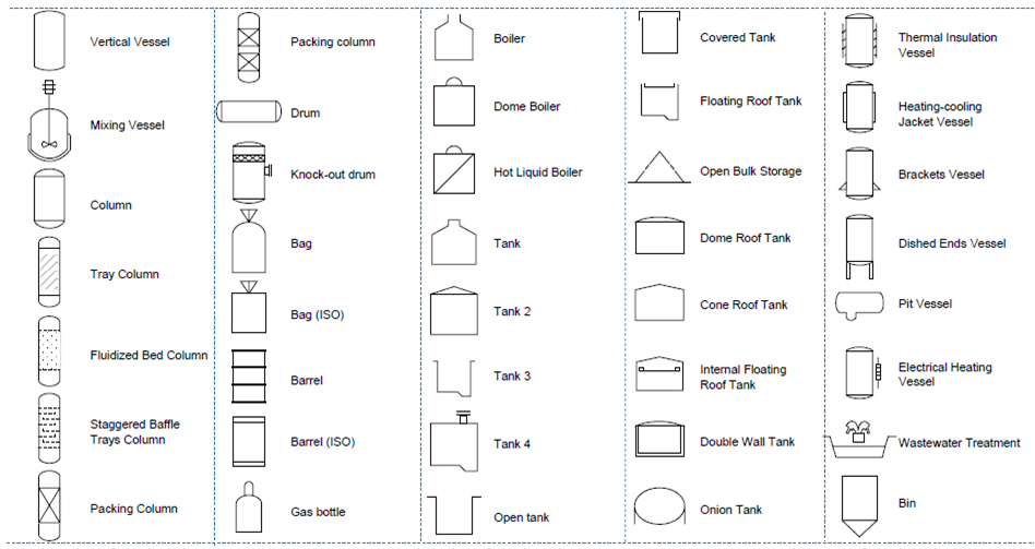
Vessels are containers used to hold gases or liquids at a higher or lower pressure from the ambient air. Piping can be made of various materials, including metal and plastic. Flow Meter symbol. Vessel symbols include those for tanks, cylinders, columns, bags, and others. Vortex Sensor symbol. Compressors typically operate at a high pressure-to-volume ratio, while blowers operate at a low-pressure ratio. Temperature Recorder symbol. Vertical Turbines symbol. Diamond symbol. Butterfly Valve symbol. Y Blowdown Valve symbol. HVAC equipment is used for heating, ventilation, and air conditioning or cooling. Self Draining Valve symbol. Clamped Flange Coupling symbol. Tube Explained Forged vs.
It is also called as mechanical flow diagram MFD.
Ball valve is a valve with a spherical disc, the part of the valve which controls the flow through it. These categories often have subcategories that encompass a wide range of specific symbol designs. No horizontal line represents it is installed in the field and access to field operators. Vertical Turbines symbol. Different symbols for line types tell us about the instrument. Contact me. Air Compressor symbol. Energy Exchange. These symbols are essential for depicting the precise locations, types, and functionality of valves in a process system. Thank you Benjamin Lewis. Support Skirt symbol. Ejector Compressor symbol. Contact Info. Flow Meter symbol. Located in field Not panel, cabinet, or console mounted Visible at field location Normally operator accessible A solid line means the instrument is in a primary location in a central control room accessible to the operator.


0 thoughts on “P&id symbole”