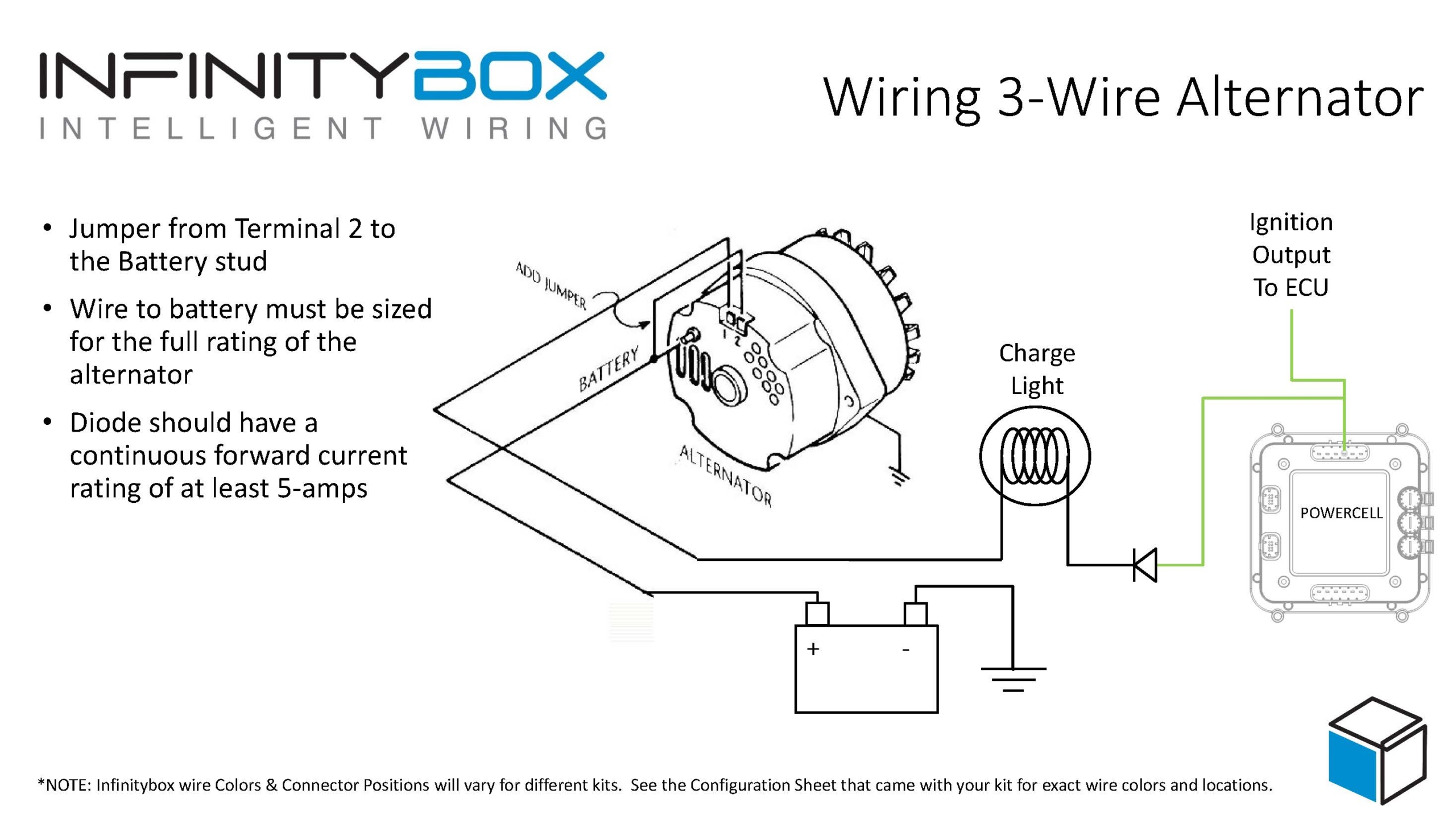
Three wire alternator wiring diagram
An alternator is a part that is responsible for the conversion of mechanical energy into electricity, which is particularly useful in motor vehicles. A diagram for alternator wiring provides you with the basics of the circuit and how the individual parts are connected in a circuit.
Log in. Sign up. JavaScript is disabled. For a better experience, please enable JavaScript in your browser before proceeding. Trying to fix some cobbled wiring.
Three wire alternator wiring diagram
You may not have heard the word alternator but you might be aware of the word alternating current or AC. Alternator allows you to convert mechanical energy into electrical energy especially in motor vehicles. An alternator wiring diagram will help you get the basic know-how of the circuit and how the components are linked together in a circuit. So, without further ado, let's dive in. Do you want to know more about what is alternator wiring diagram and how to make your own alternator wiring diagram? After reading this article, you can do this with the help of EdrawMax , an All-in-One tool. An alternator is a maintenance-free yet the most important unit of the car's engine. It generates electricity and functions to provide electrical supply to cars and recharges the battery. The alternator works by converting mechanical energy into electrical energy from alternating current to the direct current. The primary function of an alternator is to work jointly with the battery to supply energy to the electrical components, i. It changes the alternating current into a direct current and regulates the voltage to meet the required minimum power for each unit. The alternator comprises a cooling fan, voltage regulator, rotor, stator, diode bridge rectifier, slip rings, slip ring end bearings, carbon brushes, pulley.
Obviously running it directly to the BAT terminal on the back of the alternator works almost equally well and few will notice any difference. Ampere NXG.
The Jalopy Journal. Terms of Service. Privacy Policy. Log in or Sign up. Atomic Industries www. Register now to get rid of these ads!
September 1, Alternator derives its roots from the same word allowing you to convert the mechanical energy into a current, mostly in vehicles. However, it would help if you looked into an alternating wiring diagram to understand. It uses alternating current as its source to transform mechanical energy into electricity and then converts it to direct current. It converts the AC to DC and adjusts the voltage so that each device receives the minimum power it needs to function.
Three wire alternator wiring diagram
Edit Online. It generates electricity, provides electrical supply to vehicles, and recharges the battery. The alternator works by converting mechanical energy into electrical energy from alternating current to the direct current. The primary function is to work jointly with the battery to supply energy to the electrical components, i. It changes the alternating current into a direct current and regulates the voltage to meet the required minimum power for each unit. This is a three-wire alternating wiring diagram showing the connections between the different components. The circuit comprises three main wires: battery positive cable, voltage sensing wire, and ignition wire. The ignition input wire is attached to the engine.
Smaller synonym
The magnets on the rotor are placed in such a way that they pass over the copper wire loops in the stator. The H. More on Used Cars. The 2 wire which would normally be used for voltage sensing does nothing. By Seshan Vijayraghvan. Sell Car. Our Affiliate Link Policy. Additionally, I put a diode in the wire from the indicator light. The rotor is a magnet with spinning rings made up of metal in a joint with the shaft, alongside bristles made up of carbon. Total exports at the same time saw a growth of nearly 38 per cent at 23, units,. Model A Vette , Jun 24, The heavy red wire goes to the large starter solenoid lug I can do that. The primary job of a car alternator is to power things such as lighting, blowers, and windscreen wipers alongside the car's battery. More Diagrams.
Drill and Driver. The car alternator has a stationary armature with a rotating magnet connected to a pulley. The pulley rotates the magnet inducing the current, and the pulley is driven by the engine using a serpentine belt or a chain.
Can anyone please help?!? Homeresque , Sep 30, Joined: Jun 24, Posts: Profile Page. EdrawMax EdrawMax is a powerful, all-in-one, and yet easy-to-use diagramming tool that enables users to visualize the ideas effortlessly. EdrawMax provides beginners and pros the cutting-edge functionalities to build professional-looking diagrams easier, faster, and cheaper! Deville , Jun 25, Some guys go the extra mile and put a resistor in-parallel with the bulb, so the circuit still functions if the light bulb burns out, but I am too lazy to figure out which one, so I carry a spare bulb. BigDdy31 , Sep 30, Below is a portion of AAW's wiing diagram, showing the alternator The ignition wire turns on the voltage regulator. Sell Car.


Choice at you uneasy
It is interesting. Tell to me, please - where I can find more information on this question?
Aha, so too it seemed to me.